// project
BentoBot
Overview
BentoBot is two-wheel differential drive mobile robot with an autonomous sensor suite including wheel encoders, IMU, and 2D LIDAR. This robot initially started as a challenge for myself to design, build, and program a robot from the ground-up using consumer/hobby electronics parts. This involved delving into concepts which I was not intimately familiar with, such as CAD and 3D printer manufacturing. I also aimed this project to be a way to practice and improve my C++ abilities. This project is currently ongoing, currently working on designing/implementing a custom simultaneous and localization package for this robot.
General Design
The first step of the design process was identifying the purpose of this robot and when the project could be considered “finished”. For me, this robot’s purpose is to teach me more about intricacies in the full-stack robotics development process. Namely, this project will be complete once the robot is assembled and it is able to map, localize, and path plan with my custom written software. Due to this requirement, and due to my inexperience CADing a full robot, I opted to go with a robot design I have worked with before - a two-wheel differential drive robot with three sensors: wheel encoders, IMU, and LIDAR.
Electrical Design
Soon after determining what sensors I needed, I went to work on the electrical design, determining all sensors I would utilize and determining their interfaces to communicate/control each of them. I purchased the following:
- Jetson Nano - the Computer that would run ROS and interface with the MCU
- Teensy 4.0 - the MCU for motor control and IMU data
- LD06 - the 2D LIDAR used for range measurements
- MPU6050 - the IMU for angular velocity measurements
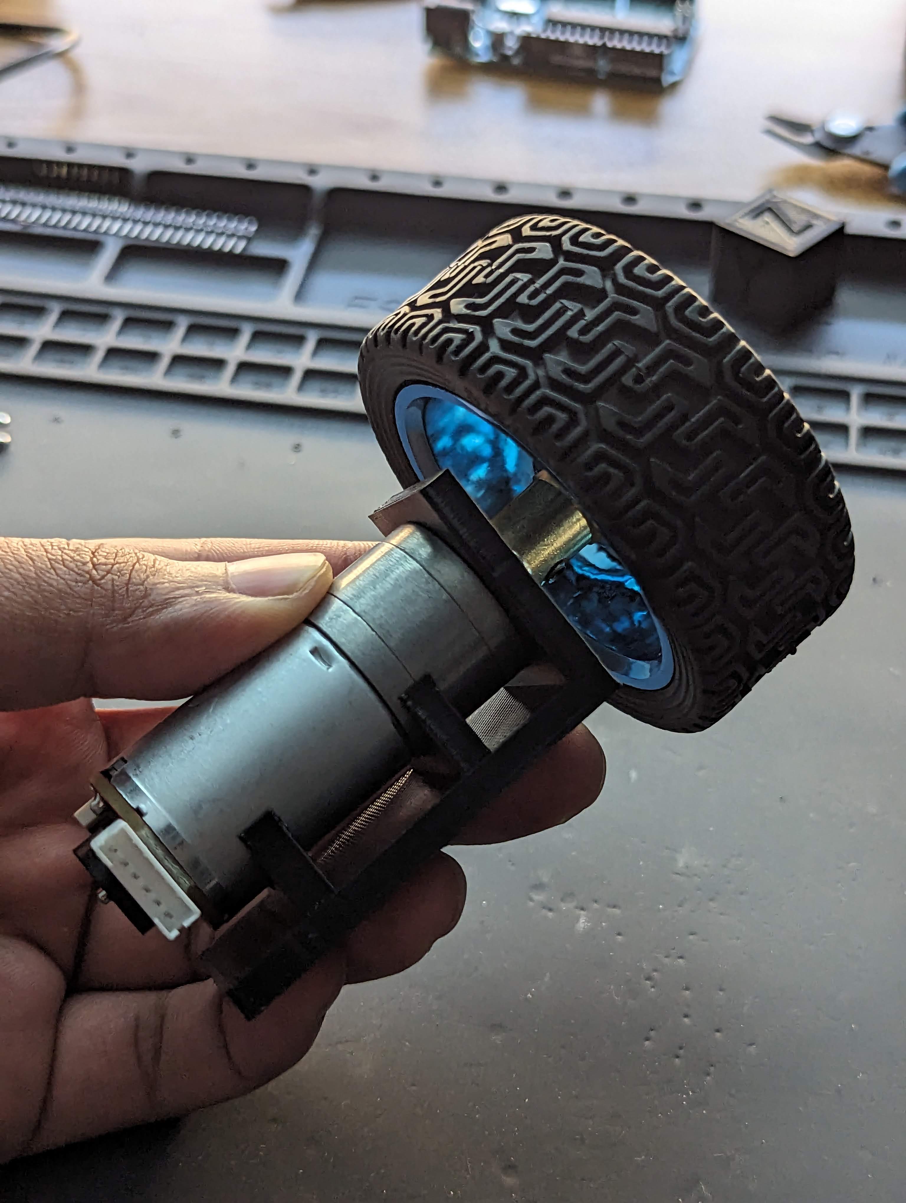
- 12V DC Motors w/ Encoders - main actuation for the robot, came with built-in rotary encoders
- L298N DC Motor Driver - PWM-based motor controllers for the DC motors
- 2200 mAH 3S 50C LiPo - battery for powering all components
- XL6009 Boost Converter - boost converter to convert LiPo voltage for DC motors
- 12V to 5V Buck Converter - buck converter to convert LiPo voltage for Jetson Nano
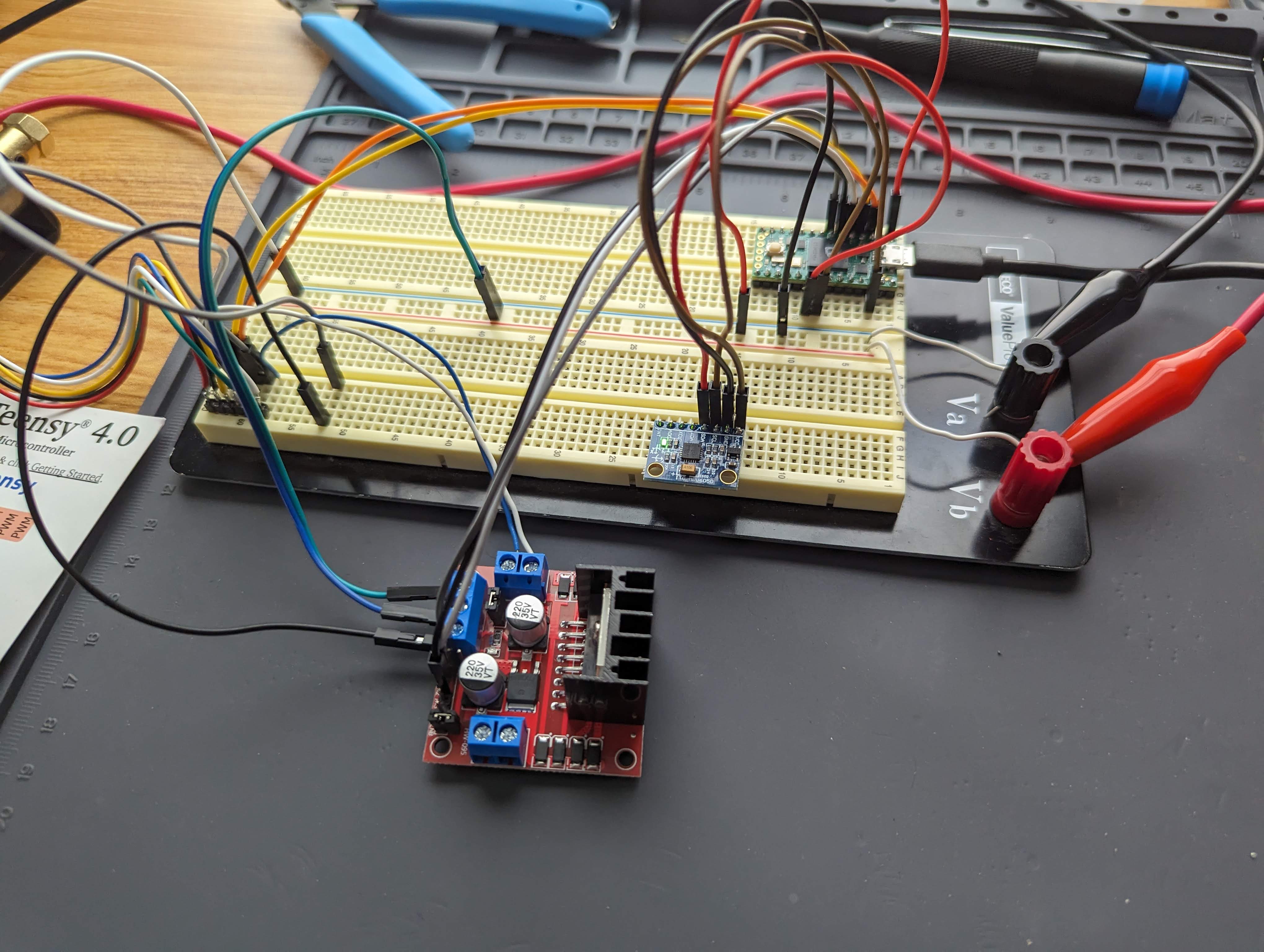
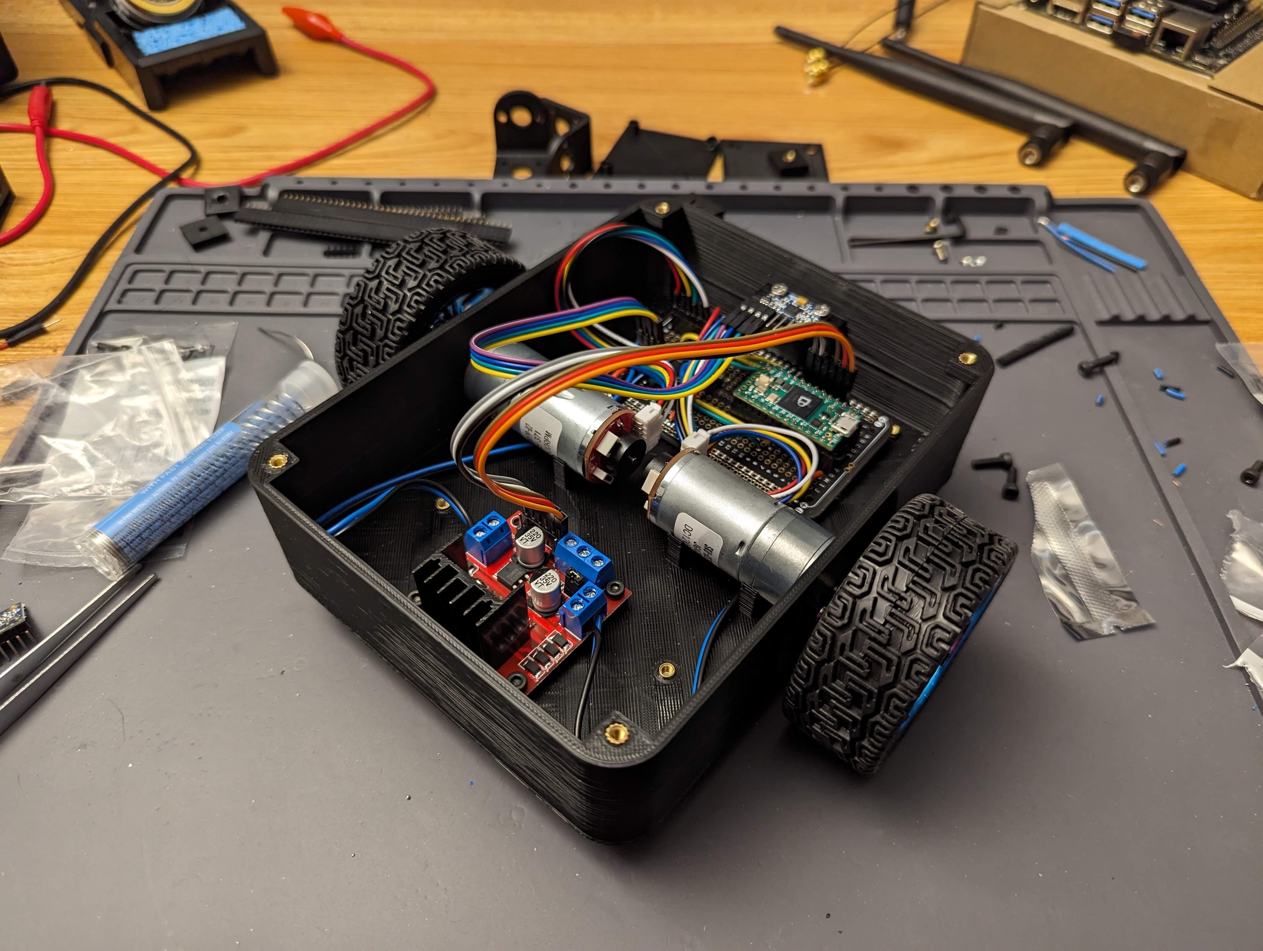
After purchasing these components and other necessary electronics components (power supply, soldering iron, protoboards, etc.), I went to work with making an electrical prototype. My first prototype was to ensure that I can read raw data from the IMU and the motor encoders as well as send PWM commands to the L298N motor controller. I wrote and uploaded a C++ sketch to the Teensy 4.0 (PlatformIO is so nice for this), showing that I was able to get raw data with the wiring scheme shown below:
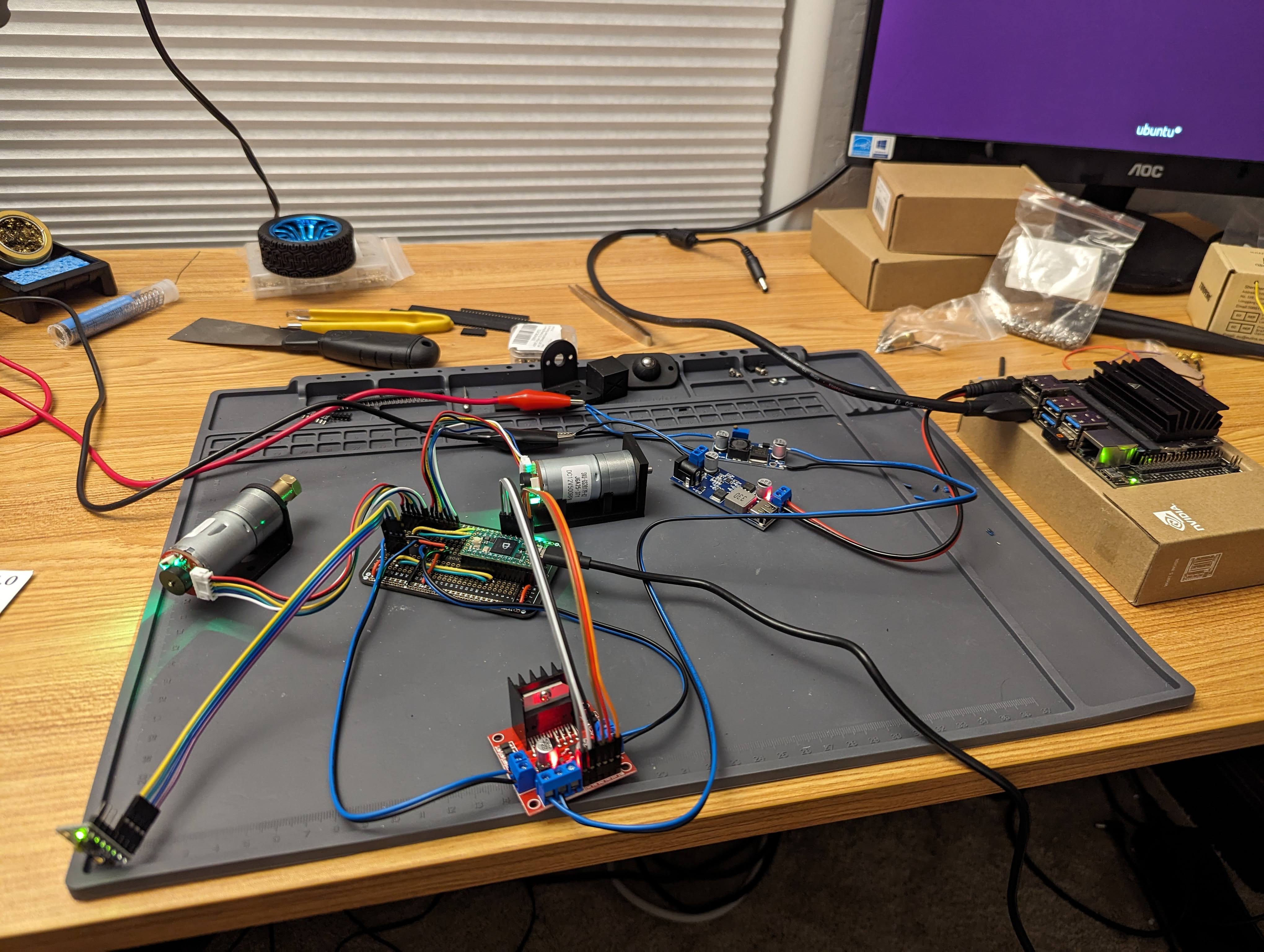
Afterwards, I tested and hooked up the voltage regulators to ensure that the battery voltages (at this stage simulated by the power supply) were converted properly and adjusted to the range of voltages (11.1V - 12.6V) given by the LiPo battery in its capacity cycle. During this test, I realized that setting the motor voltage to 12V with the boost converter would result in varying input motor voltages as the battery voltage increased to it’s max of 12.6V. As a result, I decided to change the voltage to 13V. Prior to assembly, I did an unmounted power test to ensure that the 3S LIPO could power all the components while the motors and LIDAR are active.
IMU Calibration
Typically IMUs will have some offset when reading their value. In order to account for this offset, we can simply measure the offset while keeping the IMU still and subtract this offset when we are reading the IMU. Fortunately, Adafruit’s MPU6050 library provides a calibration sketch, allowing me to quickly calibrate the sensor.
Motor Calibration
The motor calibration, however is more complex. In this context, calibration is specific to my implementation of the control mechanism. I utilized an Extended Kalman Filter to estimate and filter the velocity of the motor with the rotary encoder measurements. To control the velocity of the motors, I utilized a PID controller with a feed-forward component to convert a desired velocity value to a PWM signal that would be sent to the motor driver.
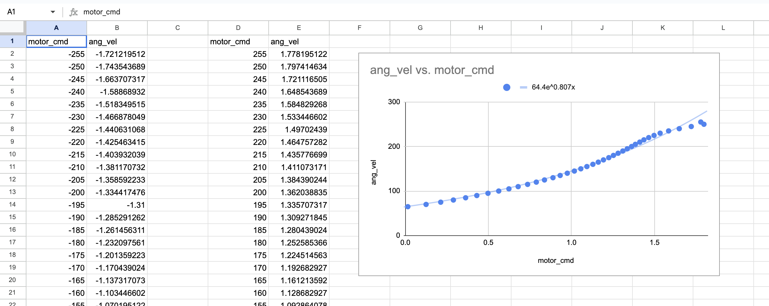
To calibrate this controller, I wrote a Teensy sketch to read PWM signals from Serial (as well as reverse direction signals) and send them to the motor drivers. This sketch would then output the estimated velocity from the Kalman Filter to Serial. With a Python script, I looped through all possible PWM values and recorded the estimated velocities to a CSV.
Using this data, I utilize Google Sheets to fit an exponential (the best fitting approximation) to convert velocity to PWM. As expected, the trend line was vertically reflected for negative velocities. I used this procedure to calculate an effective feed-forward component to the PID controller. To tune the other constants, I utilized the Ziegler-Nichols method for PID tuning.
Mechanical Design
For the CAD, I opted to use Onshape as it has a feature-rich free tier and is browser-based, allowing me to utilize the software without needing to install software on different computers I use for development/testing/printing.
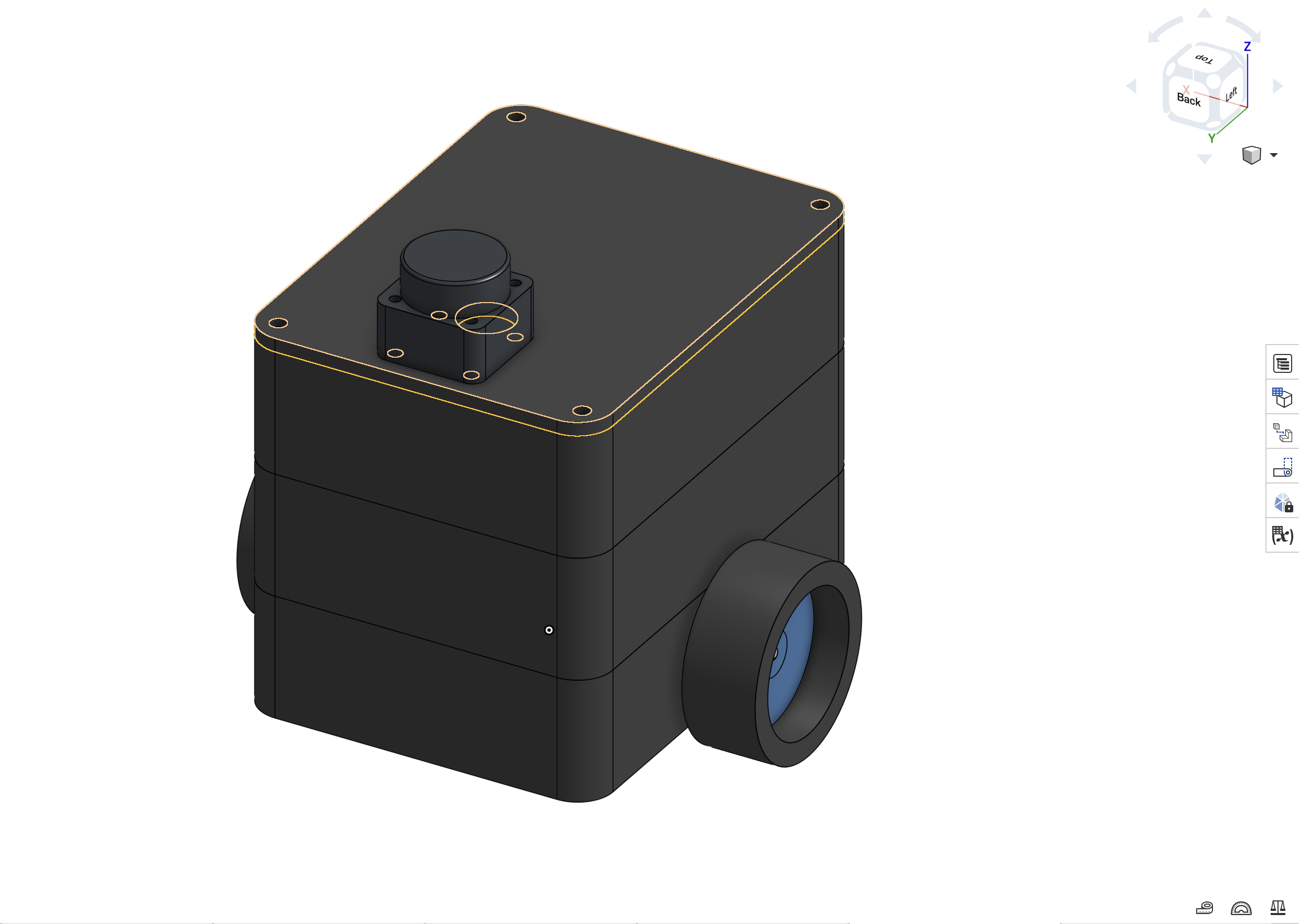
My strategy was to split the robot into different tiers, with each tier containing different components. On the first tier, I would have the motors, motor controller, IMU, and Teensy. The second layer would have the battery and power distribution boards. The third layer would contain the Jetson Nano. Finally, the top of the robot would contain the 2D LIDAR.
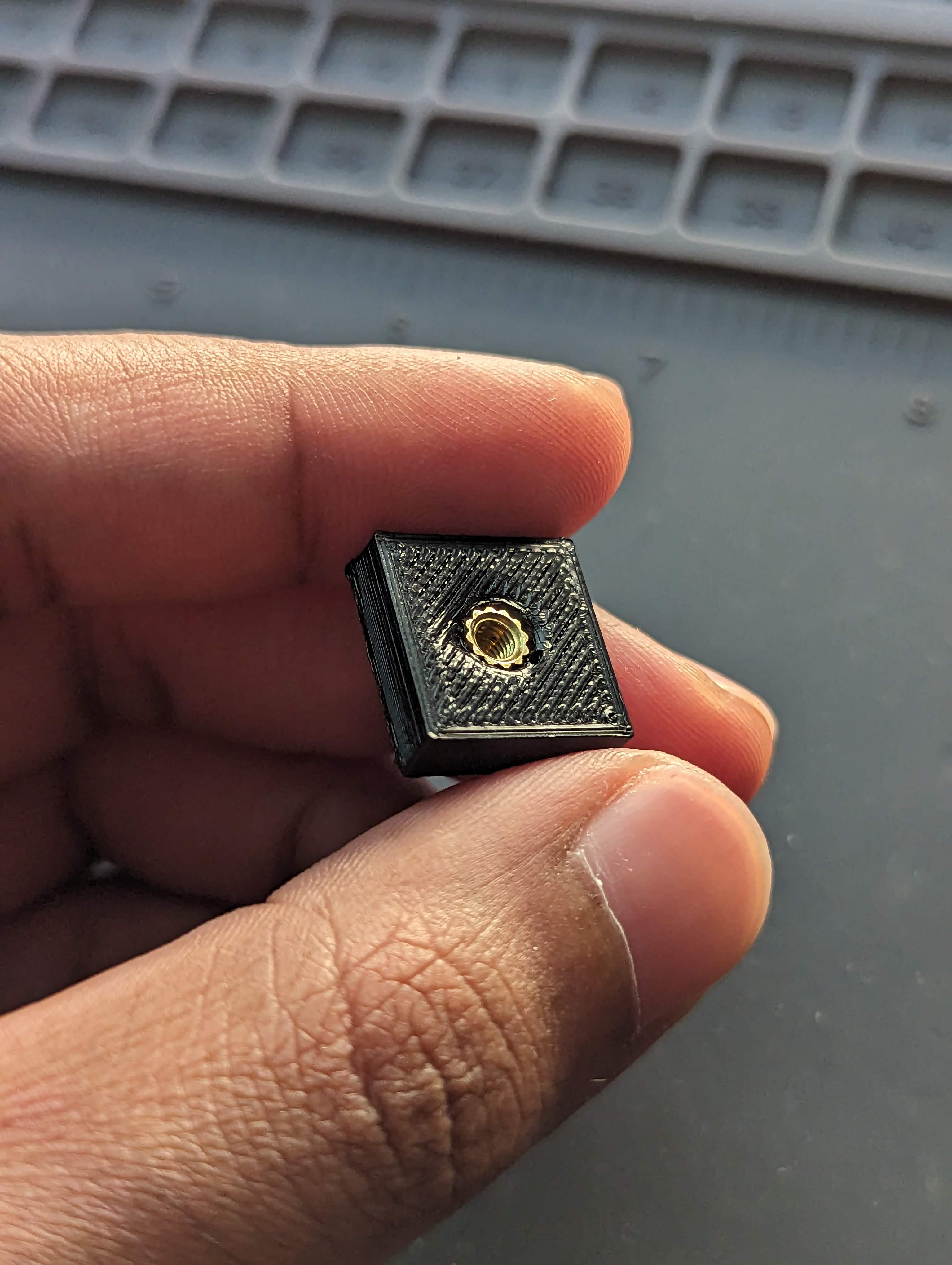
Prior to designing the robot itself, I designed and 3D printed various test pieces to ensure proper fit for the brass threaded inserts, the motor mount, and sensor mounts. This allowed me to ensure that all of the sensors and actuators would be able to mount properly before I spent a long time printing out the larger piece.
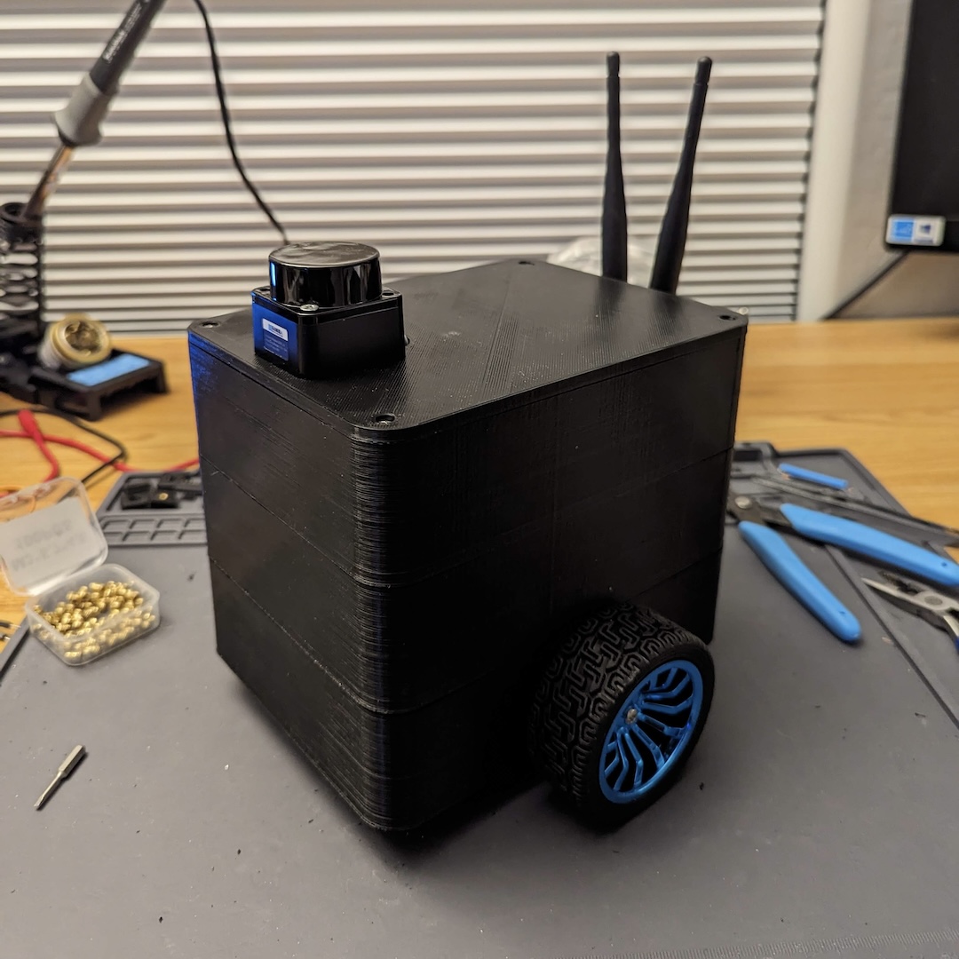
The full CAD and the assembled robot is shown below:
Software Design
Bentobot’s software backend uses ROS Kinetic. The software portion of this project is still under development. The goal of this project is to write custom localization, mapping, and path planning packages. At the moment, I have written a dead reckoning localizer that utilizes a Kalman Filter to fuse odometry and IMU information into a more accurate localization estimate.
I am currently working on the next step, designing and implementing a mapping algorithm. I am interested in pursuing a graph based solution, utilizing the 2D scans and odometry estimate from the dead reckoning localizer to build a frontend and utilizing an existing C++ graph solver library (g2o) to optimize the backend.
Learn More
To delve into more specifics of this project, please visit the GitHub repository here.