// project
The Atlas Project
Unique to Carnegie Mellon University, buggy is a competition where Greek and independent organizations race with their buggies, small, low, aerodynamic vehicles, powered only by gravity and human pushers. Traditionally, students are recruited to drive these on the course. In the Atlas Project, our goal to make a buggy that can drive itself around the course using only the limited knowledge we can get from our sensors.
The project had grown significantly from its origins as a crazy idea fulfilled by two enthusiastic roommates, now garnering a small following. I was not one of the founders of this project; I joined two years after its founding, a freshman looking for a way to make a mark on campus. From then on, I worked my way up, becoming the president of the project and leading it to its recognition as a student organization.
RoboQuasar
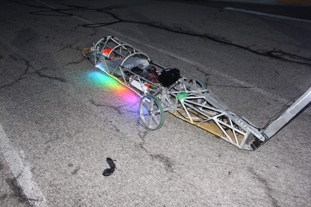
When I joined the project, work was taking place to retrofit Quasar, an old aluminum frame and shell buggy built to race in 2002, into an autonomous platform (now known as RoboQuasar). I was still new to the project, so I spent this year starting to learn about the ins and outs of robotics programming.
Hardware Issues
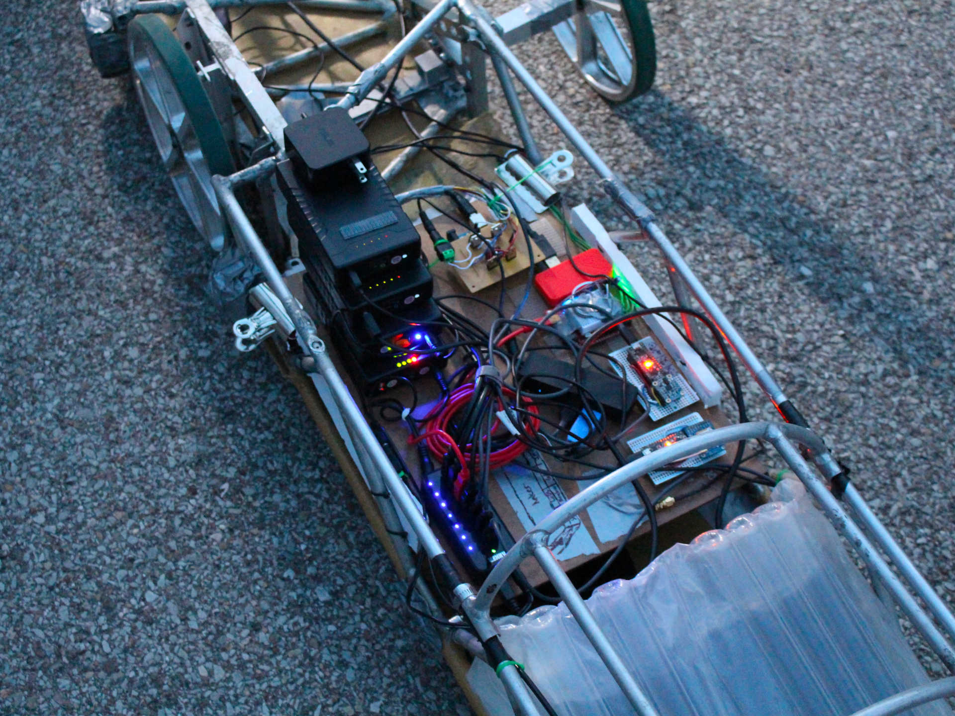
We built RoboQuasar with the following:
- Steering system powered through timing belt and stepper motor.
- Integrated Measurement Unit (IMU) to measure orientation.
- GPS to measure position.
These three things would (hypothetically) give us all we need to figure out where we are and actuate the buggy to where it needed to be. However, we ultimately found many issues with this setup, specifically in the steering and GPS.
First off, our steering system was driven by a stepper motor connected to a large circular bearing with a timing belt. Since we were using a stepper motor, we were able to get fast and accurate turns with the motor. However, Quasar was not built with suspension, and as a result, was a very bumpy ride. This caused issues with our timing belt setup, often resulting in stepper skips and looseness in the belt, despite attempts at tightening it.
Further, the consumer GPS we used (Adafruit Ultimate GPS Breakout) had trouble on certain parts of the course. The buggy course is pictured below:
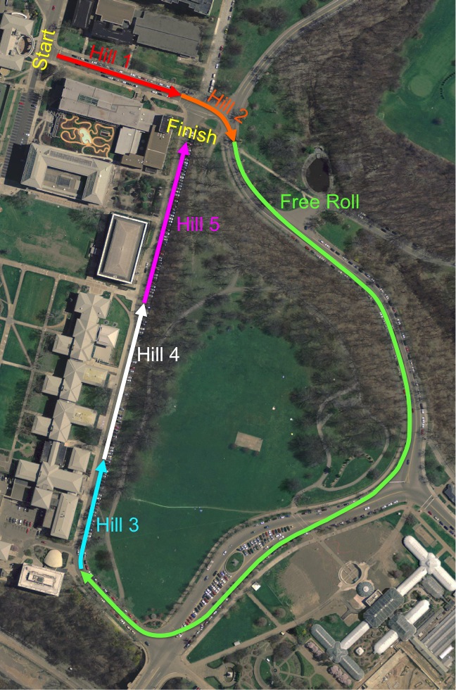
In the image above, we can see that hills 1, 3, 4, and 5 are very close to buildings. These buildings caused interference with the GPS signal, resulting in faulty readings and sometimes no readings at these positions. Further, in the first half of the free roll, the track is covered by many trees. These trees further block the receiver’s reception to the satellites, leading to spotty reception on the course.
Localization Troubles
At the beginning, in 2016, we had not tested for these fundamental issues, ultimately resulting in issues down the line. Instead, we put all of our effort (our team was around five people at the time) into determining how to localize the buggy on the course.
This year, we utilized just the GPS as our localizer. However, for reasons listed above, the frequency with which we received GPS data was certainly not ideal, leading to a relatively significant delay on our localization as well as some drift for certain portions of the course. To account for this drift, we started at the same spot at the beginning of the course. We noted this position and given the first few measurements of the GPS, we calculated a bias value that we used for the entire course.
Further, the IMU gave us an angle relative to where the device was started. To bring this angle into a global frame, we used a compass to calculate the angle at the beginning of the course whenever the buggy started. This was used as an additional bias to the sensor data.
Using this fairly simple method, we were sometimes able to get decent localization estimates around the course. However, certain areas of the course still proved to have significantly different drift and localization attempts were not consistent.
Controlling RoboQuasar
For the controller, we used a very simple controller. Since our state estimate was in longitude and latitude, we could use google maps to give us waypoints along the course. These waypoints gave us locations where we wanted RoboQuasar to be. The estimator above (primary GPS and IMU) gave us our position and orientation on the course. Our controller simply pointed the steering at the next waypoint given our current position.
This method of controller and estimator worked sometimes. However, it was very volatile. One wrong measurement could call disaster for the entire system. We were actually able to get one fully autonomous run around the course, with some crashes.
BabyBuggy
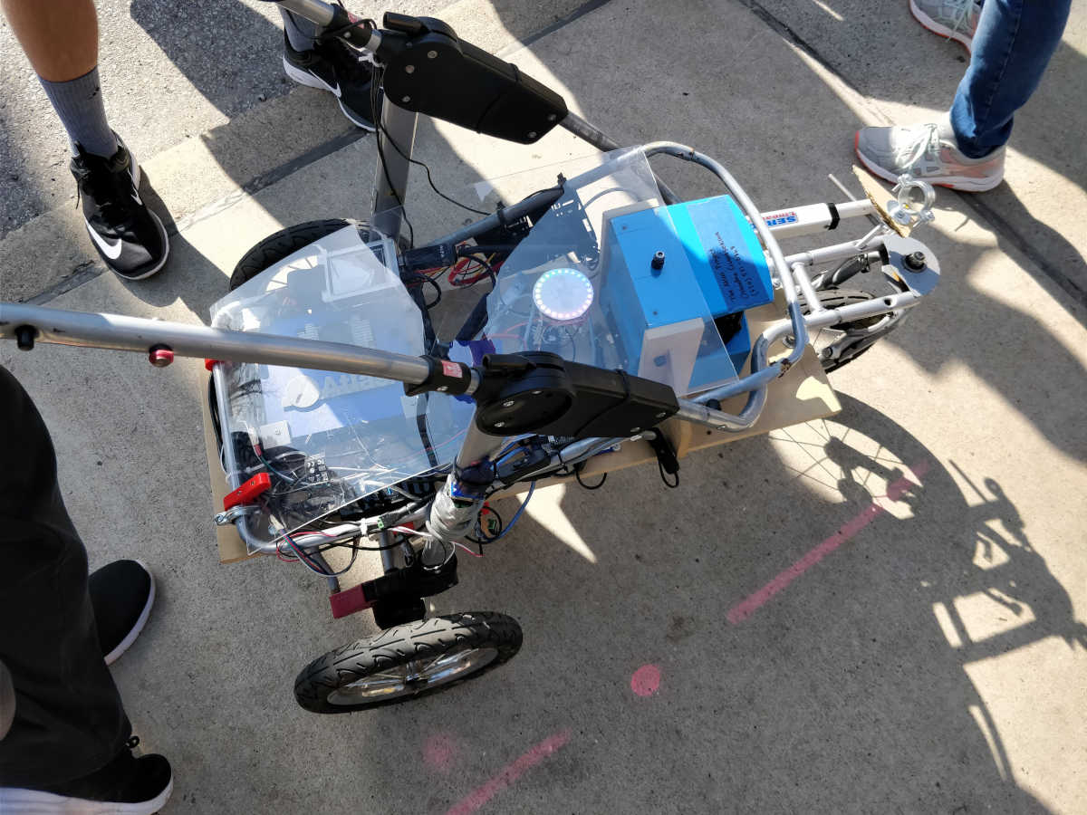
The following year, in 2017, after our experience with RoboQuasar, we came to the conclusion that we did not have enough sensors to properly localize and control the buggy. Again, due to lack of significant funding, we decided to retrofit. This time, however, we came across a baby stroller in a Massachusetts junkyard. We also came across a LIDAR being sold on eBay for $800, a solid deal for us! So, in the end, the aptly named BabyBuggy was built with the following:
- Linear actuator for steering.
- Integrated Measurement Unit (IMU) for relative orientation.
- GPS for latitude/longitude position.
- Two wheel encoders for velocity and distance estimation.
- LMS200 LIDAR sensor for range measurements.
The priority for this year was building the buggy, so a significant portion of our team was unable to work on the development of software.
Dead Reckoning
In 2018, however, we began to get a better idea of how to approach this problem. After researching the localization problem, we came up with a few methods of localization:
- Pure GPS Localization
- Dead Reckoning w/ GPS bias
- Dead Reckoning w/ no bias
From our experience in 2016, we realized that purely GPS-based localization would cause issues on the course, so we were more focused on the Dead Reckoning solutions. In the end, we were able to make a simple velocity estimator with the encoders by utilizing a first order filter. Using this velocity estimate and a relative yaw, pitch, and roll from the IMU, we could systematically estimate our position and orientation in 3D by doing the following update (pulled directly from our dead reckoning code):
yawMatrix = np.matrix([
            [math.cos(yaw), -math.sin(yaw), 0],
            [math.sin(yaw), math.cos(yaw), 0],
            [0, 0, 1]
            ])

pitchMatrix = np.matrix([
            [math.cos(pitch), 0, math.sin(pitch)],
            [0, 1, 0],
            [-math.sin(pitch), 0, math.cos(pitch)]
            ])

rollMatrix = np.matrix([
            [1, 0, 0],
            [0, math.cos(roll), -math.sin(roll)],
            [0, math.sin(roll), math.cos(roll)]
            ])

R = yawMatrix * pitchMatrix * rollMatrix
vel_mat = np.matrix([[state[3]], [0], [0]])

transf_vel = R * vel_mat

cur_time = rospy.get_time()
dt = cur_time - prev_time
prev_time = cur_time

state[0] = state[0] + transf_vel[0,0]*dt
state[1] = state[1] + transf_vel[1,0]*dt
state[2] = state[2] + transf_vel[2,0]*dt
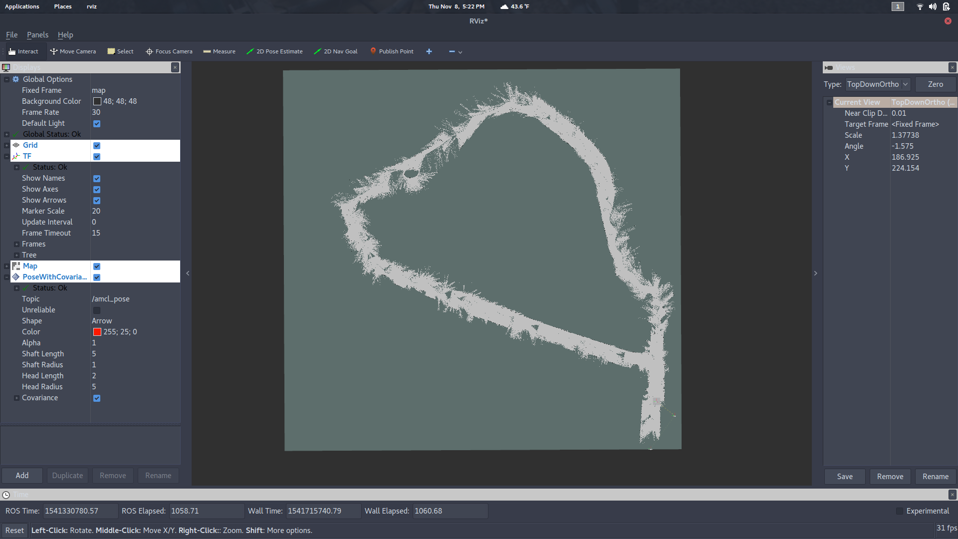
We fed this dead reckoned estimate into a ROS package known as gmapping. With a lot of tuning, we were able to get a decent map of the course. However, this map still has some loop closure issues, likely caused by lack of sufficient data. We are working on making a better map with clearer features.
We are currently working on the controller for BabyBuggy. We plan to roll BabyBuggy again during the 2019 Sweepstakes (Buggy) competition.
DuneBuggy
DuneBuggy is our newest autonomous platform. Currently, it is still under construction. The chassis is made from a Razor Dunebuggy that was found on Amazon. We are planning to utilize all we learned from past years in this retrofit.
Resources
All the software for this project can be found in our GitHub Organization.